
Tunnel Boring Method, a.k.a. Pipe Jacking Method
Application
Conventional Tunneling/Pipe Jacking is a one pass method for installing reinforced concrete pipe (RCP) to typically serve as a storm sewer. Tunneling can also serve as a two-pass method for installation of large diameter steel casing to facilitate a carrier pipe over long distances that would exceed the typical limits of the Auger-Boring method.
Pipe Material
- Reinforced Concrete Pipe - diameter range – 42" I.D. to 12' I.D.
- Steel Casing Pipe – diameter range - 48" O.D. to 14' O.D.
Drive Lengths
Range from 25 LF up to 800 LF.
Soils
The tunnel boring machine has (4) cutter head configurations:
-
Dirt cutter bar for tunneling through clay and sandy clay soils.
-
Carbide tipped, 'bullet' teeth cutter bar for tunneling through harder clays or soft rock/shale.
-
Sand shelves for tunneling in dry/dewatered sand soils.
-
Closed Face Attachment for tunneling through varying and unstable ground conditions.
Description
-
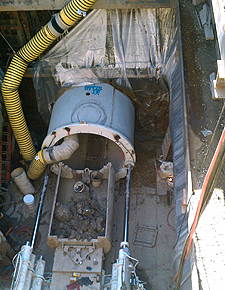
The RCP/steel casing pipe fits into a receiving band at the back of the tunnel boring machine (TBM) and the TBM together with the following lengths of pipe are thrust (pushed) forward by a hydraulic jacking frame, located in the drive or working shaft, as the TBM excavates the soils. The excavated soils are transported by a haul train to the working shaft and hoisted to the surface grade for disposal off-site.
-
Keefe will determine which cutter head configuration should be used for excavating the tunnel based on information from soil boring logs and confirmed by actual soils observed during excavation of the work shaft.
-
Line and grade of the tunnel's advance shall be continuously monitored by a laser guidance system, which is checked by conventional surveying instruments. Steering of the TBM to maintain horizontal and vertical alignment is accomplished by the operator who is working in the TBM. The TBM's two piece construction permits it to articulate 360 degrees.
-
The RCP/steel casing lengths will be placed behind the TBM, and jacked-in-place. A plywood cushion is placed in each joint of the Reinforced Concrete Pipe to evenly distribute the jacking load across the entire bell/spigot. Steel casing lengths are joined by welding.
-
If necessary, a bentonite lubricant will be pumped through the national pipe thread (NPT) fittings, cast/welded in the wall of the pipe to reduce soil friction on the outside wall of the pipe. If required, upon completion of the tunnel drive, the annular space between the outside wall of the pipe and the tunnel excavation shall be contact-grouted.